Here is a link that showcases my Portfolio.
Author: Isaiah Dupree
How does Weight Affect a Rocket’s Flight Trajectory

Missions or flight regimes that are carried out with rockets are optimized to have certain parameters like Delta V, range, time to target, altitude and etc.

The thrust profile is important to consider when talking about rocket weight. Thrust profiles in some rockets are not constant and this directly affects the flight profile and can give information on what type of mission that the rocket is designed for.
Here is an equation to highlight that is directly impacted by the changing mass of a rocket.

Where m_0 is the initial mass, m_f is the final mass, Delta V ideal is the ideal velocity increment, g_0 is gravity at sea level, and I_sp is the specific impulse of the propellant.
The ideal velocity is how much velocity is imparted to the system. The specific impulse is a parameter that explains how efficient a propellant is and is in the units of seconds. It is composed of Force divided by the mass flow rate times gravity.

A specific impulse of 120 seconds will provide an impulse of 120-pound seconds per pound of propellant. The area underneath the thrust vs. time is a way to calculate impulse.
The internal propellant mass of the rocket will be decreased on ignition.
If the rocket uses a solid propellant, then its internal burn area will increase based to the rocket’s grain geometry. The specific impulse can vary from the changing burn area.

This is figure 11-16 from George Sutton’s “Rocket Propulsion Elements.”
Neutral grain geometries have thrust profiles that are constant after ignition. Progressive and regressive grain geometries have thrust profiles that either increase after ignition or decrease after ignition, respectively.
If the rocket uses liquid propellant, then the mass of the propellant and oxidizer tanks will decrease and are filled with a pressurant gas.
The maximum thrust to weight ratio is achieved right after burnout with rockets with a constant thrust profile.
The exhaust fumes at the rocket’s nozzle may also affect the coefficient of drag of the rocket with changing altitude which can add the drag force at those altitudes.
Another point to mention is that to reach greater specific impulses, the rocket will have to be split up into multiple stages. The mass required for a traditional single-stage orbit rocket is undefined.
All of these factors should be taken into account when iterating through the parameters to determine the rocket’s trajectory. Depending on how the rocket was designed, these and many other parameters may affect the location of where the center of gravity is placed within the rocket. Besides thrust, any forces of significant magnitude acting on the rocket can tilt the rocket at the rocket’s center of mass and can cause instability if unaccounted for when determining a rocket’s flight trajectory.
Two General Methods of Reducing Vibration

Tuning (Changing the Natural Frequency)
Machines have a natural frequency, and if they move, then they have a forcing frequency.
The frequency ratio is the machine’s natural frequency divided by the forcing frequency.
Machines that move also have an amplification factor, which is:

If we plot the amplification factor vs the frequency ratio, then we will be able to visually see where resonance occurs within a range of natural frequencies.

Resonance occurs when the frequency ratio is equal to 1 and the natural frequency of the system is equal to the forcing frequency of the system.
Mechanical resonance is horrible; it can lead to a machine tearing itself apart in many cases.
The frequency range around resonance is also just as bad, as it causes large unwanted amplitudes within the system. So, it is best to have a system where the natural frequency is well outside this range if possible.
This is where tuning or changing of the natural frequency can come into play, along with many other methods to reduce unwanted vibration.
The natural frequency of the machine can be changed or (tuned) so that its outside the range of resonance.
The natural frequency of a single degree of freedom system can be found with this equation:

where k is the system’s stiffness, and m is the mass of the system.
Ways to increase or decrease the natural frequency
- Increase or Decrease the Stiffness
- Increase or Decrease the Mass
In some situations, manipulating the mass of the system is not feasible so manipulating the stiffness is a method that is used more often.
The location on where to change the stiffness of a system matters because manipulating the stiffness at any nodes of the system will not do anything. It is important to change the stiffness of a system at its antinodes.
Vibration Isolation
Isolation is similar to tuning and accomplishes the same goal of reducing unwanted vibration but with a different method that includes the additional components called isolators.
Isolation deals with reducing the force of a system that is being transmitted to a foundation.
Below is a video demonstration of vibration isolation:
Vibration Isolation Demonstration – YouTube
The transmissibility ratio is the force transmitted to the foundation divided by the force of the system:

For a 1 degree of freedom system with an isolator that has damping c and stiffness k , and system mass m the amount of force transmitted to a foundation is:
This equation can be simplified by utilizing the frequency ratio, damping ratio, and the critical damping coefficient.


If we plot the Transmissibility Ratio vs Frequency Ratio then we will have a graph that looks similar to this.

Adding Isolators will change the systems natural frequency. In order to achieve Isolation, the system’s new frequency ratio should be greater than sqrt(2) and preferably even greater than that for some cases.
How to Reduce the Drag on a Rocket

Drag Force is equal to one-half the drag coefficient times density, velocity squared, and area.
There are two types of drag:
Friction Drag is the friction of an object generated by moving in a medium.
Pressure Drag is uneven pressure distribution in the direction of motion of a moving object.

The drag coefficient is a nondimensional value that describes how much drag a cross-sectional area will generate. The drag coefficient encompasses both friction drag and pressure drag. The greater the drag coefficient the higher the drag force.
Typical values for drag coefficient:
Modern automobile: 0.25 – 0.35
Flat plate: 1.28
Airfoil: 0.045
Sphere: 0.07 to 0.5
Here is a figure that shows the drag coefficients for rockets with different nose cones
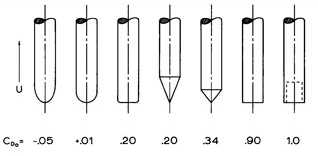
In order to reduce the pressure drag on a rocket, one would need to:
- Make the rocket as narrow as possible without hindering its structural integrity
- Optimize the shape of the nose cone so that it has the least drag coefficient
Here are some common shapes:

This is from Benson’s “Volume” from May 2017 from Nasa’s Glen Research Center.

This is from Milligan’s “Drag of Nose Cones” from 2013 published in the National Association of Rocketry
The nose shapes are ordered from generating the least drag to the most drag

This is figure 22 from Dr. Gregorek’s “AERODYNAMIC DRAG OF MODEL ROCKET” from 1970
This figure represents the pressure distribution of an ogive nose cone with a drag coefficient of 0.04
In order to reduce the friction drag on a rocket, one would need to:
- Make sure that the rocket body is smooth and that there isn’t anything impinging from the rocket body
- This will help to keep the airflow around the rocket streamlined and laminar. This will keep the boundary layer small and reduce the overall drag coefficient.
- If the rocket body is not smooth and there are protruding objects then airflow around the rocket will be turbulent. This will produce a large boundary layer leading to flow separation and increase the overall drag coefficient.

This is figure 8 from Dr. Gregorek’s “AERODYNAMIC DRAG OF MODEL ROCKET” from 1970
General tips on reducing the drag coefficient of each part of the rocket
- Nose cone
- Parabolic or ogive shape nose cone
- Body tube
- Smooth finish
- No protruding parts
- Base
- Have a tapper base of the rocket with the body to form a gentle boat tail
- Smooth out the base where the fins connect with the body
- Fins
- Airfoil shaped
- Optimize thickness
- Elliptical or tapered shape
- Align the fins properly so that they are exactly perpendicular to the body
- Good Workmanship
To elaborate further on the drag equation:
The density will decrease as the rocket increases in altitude. The higher the rocket gets, the less drag that the rocket will experience due to decreasing density.
The coefficient of drag will increase a little bit after the rocket has reached the sound barrier at Mach 1. Then the coefficient of drag will decrease with increasing Mach number.

This figure from Sutton, and Biblarz’s “Rocket Propulsion Elements” from 2016 represents the coefficient of drag with Mach number for the cross-sectional area based on a V-2 missile.

Here is another figure from Braeunig’s “Saturn V Launch Simulation” from Dec-2013 that represents the simulated coefficient of drag with Mach number for the cross-sectional area Saturn 5.
How Fast can A Rocket Bike Go?
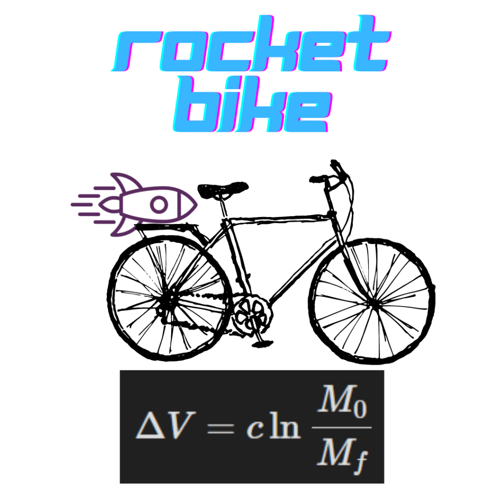
The velocity of a rocket bike depends on the type of rocket attached to the bike. More specifically, It depends on the Delta-V that the rocket can impart on the mount that is connected to the bike. Delta V is the effective exhaust velocity c of the rocket times the natural log of the initial mass over the final mass.
The initial mass will be the mass of the biker, the bike, the rocket mount, and the rocket itself. The final mass will be everything except for the mass of the propellant used in the rocket.
The change in velocity of the bike will be negligible if the mass of the propellant used is not a significant percentage of the bike’s mass.
The effective exhaust velocity can be found by multiplying the gravity at sea level by the rocket’s specific impulse.

If you take a G class rocket which is the largest rocket motor that a person can buy without needing a certification, then you’ll roughly have 160 Newton seconds of total impulse.
To go from total impulse to specific impulse, divide the total impulse by the weight of the rocket motor.
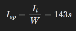
This will lead to an effective exhaust velocity of 1406 m/s.
Now you’ll need the weight before and after the rocket has spent its propellant. Let’s say that bike has a mass of 18 lbs with 175 lbs. person driving the bike. The 130 grams rocket motor and rocket mount weighs about 87671 grams. Let’s consider that mass of everything after the rocket has burnt all of the propellant is 87110 grams.

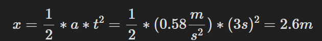
Given that the average burn time for one of these rocket motors is 3 seconds, the acceleration that the rocket will experience is

The total distance traveled, negating friction will be 2.6 meters.
Specific Heat Ratio
There are many ways to name specific heat ratio, like specific heat capacity, the ratio of specific heats, Specific Heat Coefficient, gamma, etc…
The general equation for the specific heat ratio is the Coefficient of Pressure divided by the Coefficient of Volume

gamma=(Coefficient of Pressure)/(Coefficient of Volume)

More information on the specific heat ratio for air can be found here:
https://www.ohio.edu/mechanical/thermo/property_tables/air/air_Cp_Cv.html
